音频驱动

本文档以 es8388 驱动为例。

电路原理

es8388 电路设计:

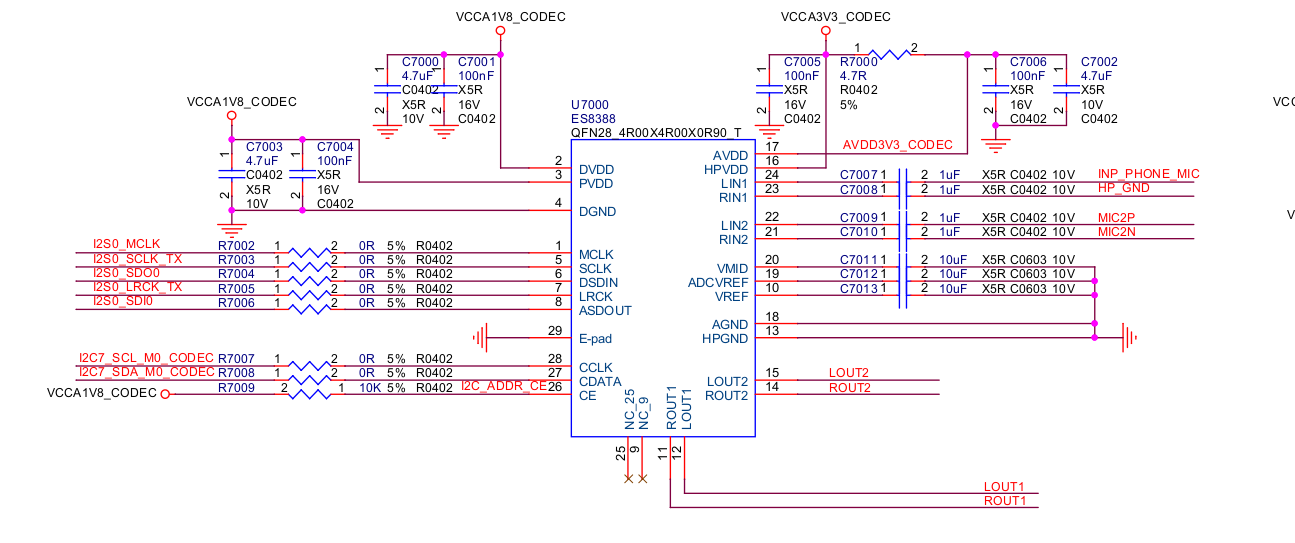
es8388 支持多种输入模式,可以直通输入也可以差分输入,这个需要针对实际情况对芯片寄存器进行配置。以上LIN1和RLIN1是直通,连接耳机。LIN2和RLIN2是差分输入,连接板载麦克风。

设备树分析

声音卡配置

1
2
3
4
5
6
7
8
9
10
11
12
13
14
15
16
17
18
19
20
21
22
23
24
25
26
27
28
29
30
31
32
33
34
35
36
37
es8388_sound: es8388-sound {
status = "okay";
compatible = "rockchip,multicodecs-card";
rockchip,card-name = "rockchip-es8388";
hp-det-gpio = <&gpio1 RK_PC4 GPIO_ACTIVE_HIGH>;
io-channels = <&saradc 3>;
io-channel-names = "adc-detect";
keyup-threshold-microvolt = <1800000>;
poll-interval = <100>;
spk-con-gpio = <&gpio4 RK_PA3 GPIO_ACTIVE_HIGH>;
hp-con-gpio = <&gpio4 RK_PA4 GPIO_ACTIVE_HIGH>;
rockchip,format = "i2s";
rockchip,mclk-fs = <256>;
rockchip,cpu = <&i2s0_8ch>;
rockchip,codec = <&es8388>;
rockchip,audio-routing =
"Headphone", "LOUT1",
"Headphone", "ROUT1",
"Speaker", "LOUT2",
"Speaker", "ROUT2",
"Headphone", "Headphone Power",
"Speaker", "Speaker Power",
"LINPUT1", "Headset Mic",
"LINPUT2", "Main Mic",
"RINPUT1", "Main Mic",
"RINPUT2", "Main Mic";
pinctrl-names = "default";
pinctrl-0 = <&hp_det>;
play-pause-key {
label = "playpause";
linux,code = <KEY_PLAYPAUSE>;
press-threshold-microvolt = <2000>;
};
};

label解释:
hp-det-gpio :检测耳机插入状态的GPIO
io-channels :检测耳机插入状态的ADC通道
io-channel-names :检测耳机插入状态的ADC通道名称
keyup-threshold-microvolt :检测耳机插入状态的阈值
poll-interval :检测耳机插入状态的间隔时间
spk-con-gpio :耳机输出控制的GPIO
hp-con-gpio :耳机输入控制的GPIO
rockchip,format :音频数据格式
rockchip,mclk-fs :音频数据采样率
rockchip,codec :音频数据采集的CODEC
rockchip,audio-routing :音频数据采集的路由
pinctrl-0 :检测脚设置
play-pause-key :耳机播放暂停的按键

芯片挂载在I2C7总线上,对应设备树如下:

1
2
3
4
5
6
7
8
9
10
11
12
13
14
15
&i2c7 {
status = "okay";
es8388: es8388@11 {
status = "okay";
#sound-dai-cells = <0>;
compatible = "everest,es8388", "everest,es8323";
reg = <0x11>;
clocks = <&mclkout_i2s0>;
clock-names = "mclk";
assigned-clocks = <&mclkout_i2s0>;
assigned-clock-rates = <12288000>;
pinctrl-names = "default";
pinctrl-0 = <&i2s0_mclk>;
};
};

HiFi.conf中定义声卡名称

1
2
3
4
5
6
7
8
9
10
11
12
13
14
15
16
17
18
19
20
21
22
23
24
25
26
27
28
29
30
31
32
33
34
35
36
37
38
39
40
41
42
43
44
45
46
47
48
49
50
51
52
53
54
55
56
57
58
59
60
61
62
63
64
65
66
67
68
69
70
71
72
73
74
75
76
77
78
79
80
81
82
83
84
85
86
87
88
89
90
91
92
93
94
95
96
97
98
99
100
101
102
103
104
# Use case for devices on rockchip,rk809-codec card.

SectionVerb {
EnableSequence [
cdev "hw:rockchiprk809co"
]

DisableSequence [
cdev "hw:rockchiprk809co"
]
}

SectionDevice."Headphone" {
Comment "Headphones Playback"

EnableSequence [
cdev "hw:rockchiprk809co"

cset "name='Playback Path' HP"
]

DisableSequence [
cdev "hw:rockchiprk809co"

cset "name='Playback Path' OFF"
]

Value {
PlaybackPCM "hw:rockchiprk809co"
PlaybackChannels "2"
PlaybackPriority "1"
JackControl "Headphones Jack"
JackHWMute "Speaker"
}
}

SectionDevice."Speaker" {
Comment "Speaker Playback"

EnableSequence [
cdev "hw:rockchiprk809co"

cset "name='Playback Path' SPK"
]

DisableSequence [
cdev "hw:rockchiprk809co"

cset "name='Playback Path' OFF"
]

Value {
PlaybackPCM "hw:rockchiprk809co"
PlaybackChannels "2"
PlaybackPriority "2"
}
}


SectionDevice."Headset" {
Comment "Headset Mic"
ConflictingDevice [
"MainMic"
]
EnableSequence [
cdev "hw:rockchiprk809co"
cset "name='Capture MIC Path' Hands Free Mic"
]

DisableSequence [
cdev "hw:rockchiprk809co"
cset "name='Capture MIC Path' MIC OFF"
]

Value {
CapturePCM "hw:rockchiprk809co"
CaptureChannels "2"
JackControl "Mic Jack"
JackHWMute "MainMic"
}
}

SectionDevice."MainMic" {
Comment "Main Mic"
ConflictingDevice [
"Headset"
]
EnableSequence [
cdev "hw:rockchiprk809co"
cset "name='Capture MIC Path' Main Mic"
]

DisableSequence [
cdev "hw:rockchiprk809co"
cset "name='Capture MIC Path' MIC OFF"
]

Value {
CapturePCM "hw:rockchiprk809co"
CaptureChannels "2"
}
}


从配置上可以看出配置了两个 jack , “Headphone” 和 “MainMic” 。
Headphone 是用来区分耳机和喇叭播放,MainMic区分板载麦克风和耳机麦克风

数据手册

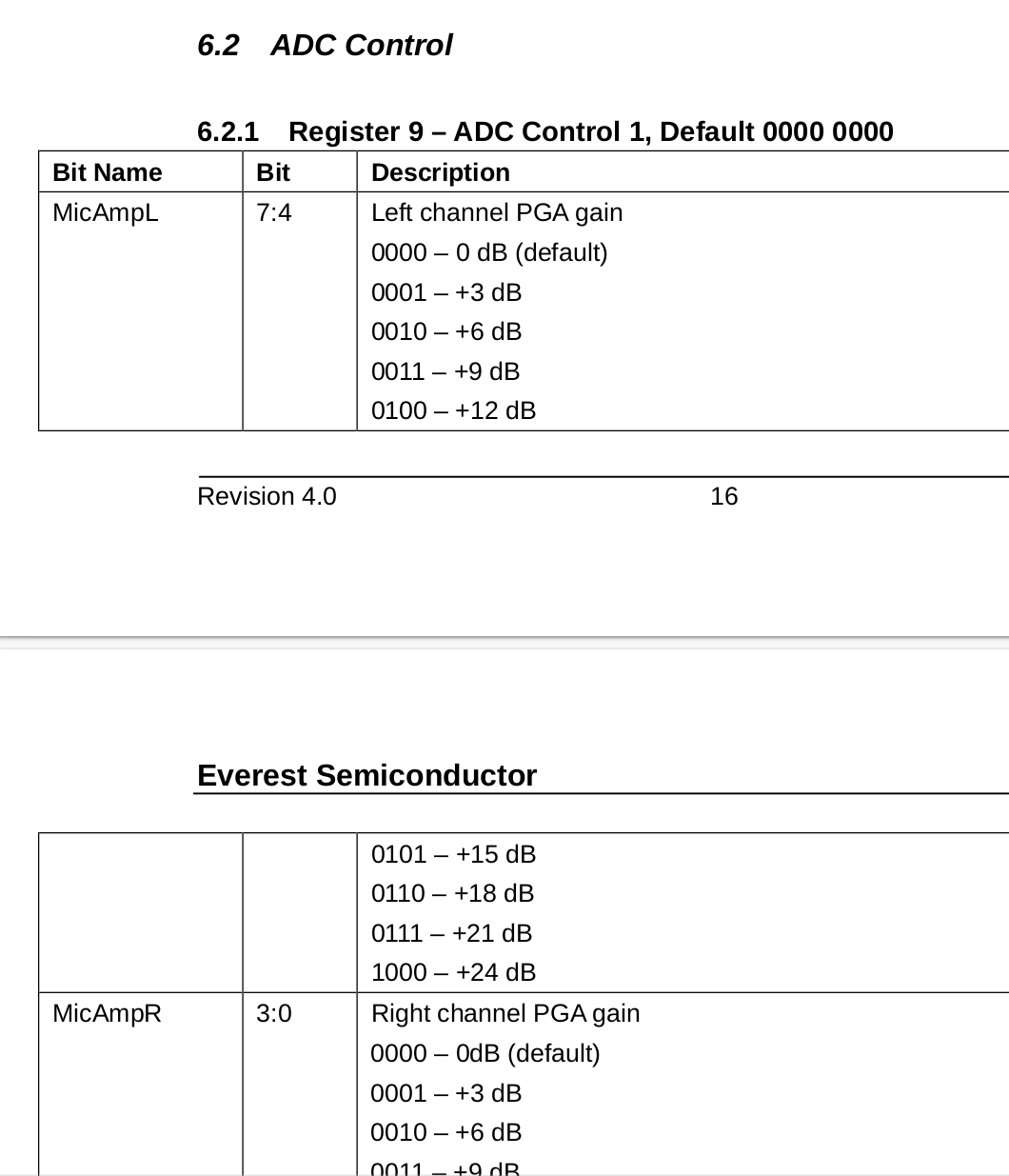
调整耳机录音增益寄存器,电路图连接的是左声道in,所以调整左声道增益就行。


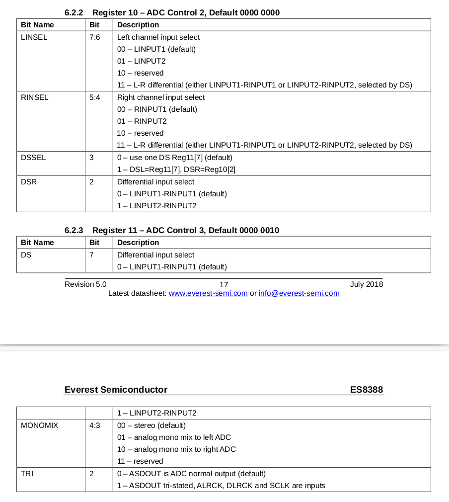
寄存器10对应的输入通道选择LIN1或者LIN2.
DSR = 0: 选择LINPUT1 - RINPUT1作为差分输入对(默认)。
DSR = 1: 选择LINPUT2 - RINPUT2作为差分输入对

寄存器11则是使用差分模式输入,DS切换需要设置成1.

驱动代码分析

代码节选:

1
2
3
4
5
6
7
8
9
10
11
12
13
14
15
16
17
18
19
20
21
22
23
24
25
26
27
28
29
30
31
32
33
34
35
36
37
38
39
40
41
42
43
44
45
46
47
48
49
50
51
52
53
54
55
56
57
58
59
60
61
62
63
64
static int es8323_probe(struct snd_soc_component *component)
{
struct es8323_priv *es8323 = snd_soc_component_get_drvdata(component);
int ret = 0;

es8323->mclk = devm_clk_get(component->dev, "mclk");
if (IS_ERR(es8323->mclk)) {
dev_err(component->dev, "%s mclk is missing or invalid\n", __func__);
return PTR_ERR(es8323->mclk);
}
ret = clk_prepare_enable(es8323->mclk);
if (ret)
return ret;
es8323->component = component;

ret = es8323_reset(component);
if (ret < 0) {
dev_err(component->dev, "Failed to issue reset\n");
clk_disable_unprepare(es8323->mclk);
return ret;
}
// 设置默认值
snd_soc_component_write(component, 0x01, 0x60);
snd_soc_component_write(component, 0x02, 0xF3);
snd_soc_component_write(component, 0x02, 0xF0);
snd_soc_component_write(component, 0x2B, 0x80);
snd_soc_component_write(component, 0x00, 0x36);
snd_soc_component_write(component, 0x08, 0x00);
snd_soc_component_write(component, 0x04, 0x00);
snd_soc_component_write(component, 0x06, 0xC3);
snd_soc_component_write(component, 0x19, 0x02);
snd_soc_component_write(component, 0x09, 0x88);
snd_soc_component_write(component, 0x0A, 0x5C);
snd_soc_component_write(component, 0x0B, 0x82);
snd_soc_component_write(component, 0x0C, 0x4C);
snd_soc_component_write(component, 0x0D, 0x02);
snd_soc_component_write(component, 0x10, 0x00);
snd_soc_component_write(component, 0x11, 0x00);
snd_soc_component_write(component, 0x12, 0xea);
snd_soc_component_write(component, 0x13, 0xc0);
snd_soc_component_write(component, 0x14, 0x05);
snd_soc_component_write(component, 0x15, 0x06);
snd_soc_component_write(component, 0x16, 0x53);

snd_soc_component_write(component, 0x17, 0x18);
snd_soc_component_write(component, 0x18, 0x02);
snd_soc_component_write(component, 0x1A, 0x00);
snd_soc_component_write(component, 0x1B, 0x00);
snd_soc_component_write(component, 0x27, 0xB8);
snd_soc_component_write(component, 0x2A, 0xB8);
snd_soc_component_write(component, 0x35, 0xA0);
usleep_range(18000, 20000);
snd_soc_component_write(component, 0x2E, 0x1E);
snd_soc_component_write(component, 0x2F, 0x1E);
snd_soc_component_write(component, 0x30, 0x1E);
snd_soc_component_write(component, 0x31, 0x1E);
snd_soc_component_write(component, 0x03, 0x09);
snd_soc_component_write(component, 0x02, 0x00);
usleep_range(18000, 20000);
snd_soc_component_write(component, 0x04, 0x3C);

es8323_set_bias_level(component, SND_SOC_BIAS_STANDBY);
return 0;
}

在probe阶段,会设置寄存器默认值,根据手册修改0x09增加录音增益。修改 0x0A和0x0B,设置默认录音路径。

问题

  • 切换录音默认路径问题

参考数据手册中寄存器10和11设置,结合代码分析。
es8388 寄存器驱动默认配置LIN1为录音设备,硬件电路板载麦克风为LIN2,如需要调试板载,需要切换以下寄存器配置值。
Left PGA Mux 32
Right PGA Mux 33
Differential Mux 34

测试

1
2
#  安装audacity 录音工具 桌面版软件
apt-get install audacity
1
2
3
4
5
6
# 查看音频设备状态
amixer -c 0 contents
# 查看声卡信息
cat /proc/asound/cards
# 设置声卡参数 如id:34
amixer cset numid=34 1
  • 指令录音
1
2
3
4
5
6
7
# 录音 
arecord -D hw:0,0 -d 10 -f cd -r 44100 -c 2 -t wav test.wav
-d 10表示录制10秒声音,test.wav是保存的文件名称

-D hw:x 表示指定第几个声卡

-r 指定采样率,-f 指定每个采样点的位数--样本大小

指令错误

1
2
3
查看参数设置,排查指令错误
arecord -D hw:0,0 --dump-hw-params

1
2
# 播放
aplay -D hw:0,0 test.wav